
Hello and welcome.
This first section will be a collection of information about Mr Bill Muller and his device.
Bills official website maintained by his daughter:
mullerpower.com
For anyone new to free energy a good place to start is:
Patrick Kelly's Pratical guide to free-energy devices
Chapter 2 contains several pages about Bill Muller's device (pg27)
Bill Muller info.Doc was posted by skywatcher123 at OU.com(reply 102)
More To Follow
Last night I read and re-read the Muller.doc posted back towards the start of the dynamo thread.
IMO this is compulsory reading for this build, A few things make much more sense to me now.
Quote
The reason the rotor does not cog or stick is because it is constantly inside the magnetic circuit created by the magnets and ferrite cores. All attraction and repulsion forces are effectively balanced causing the rotor to be turned with very little force.
"For Those Who Say: Impossible"
"The following, taken from the Encyclopedia Britannica, is for those who still find it very hard to believe that the concept of "Over Unity" or, as it is often referred to, "Perpetual Motion" is possible.
This reference is noted from the subheading:
"WORK REQUIRED TO MOVE A MAGNETIC POLE"
"When a magnetic pole is moved.WORK MUST BE DONE against any force acting on it if it is moved in the direction opposite the force, and conversely, WORK WILL BE DONE (or extracted) by the magnetic pole when it moves in the force direction. Thus, NO WORK IS DONE in moving a magnetic pole around a closed path in a magnetic field.
It follows that the WORK DONE in moving the pole ... from a point A to a point B is independent of the route followed. Otherwise (the pole) could be returned to A by another route on which MORE WORK IS EXTRACTED THAN WAS EXPENDED in the initial movement to A"
The net effect would be that WORK COULD BE EXTRACTED by movement around the complete path without any other change in the system, giving the possibility of a perpetual motion machine that is contrary to the laws of mechanics."
Wilhelm Muller's invention has No Work Required to move a pole from a pole. In other words, he has the "net effect" mentioned by the encyclopedia.
Consider the implications of this last statement?" ....
Muller also has more magnets than coils, RomeroUK has the opposite.
Parts List
Rotor
Axle --------------Got

Bearings & Housings ------------------Got
Base-plate ----------------Got
Top-plate -----------------Got
Magnets --------------Got


Threaded Supports+nuts+washers
Cores & Cheek-ends ---------Mostly constructed


Terminal blocks
Vero-board for circuits --------Have
Hall sensors+transistors+caps for drive circuits ----on order
DC-DC converter or equivalent
Large Cap.
Switches, battery, 12v Bulbs(various wattage), Panel wiring, Glue etc
RUK's invisible batteries have finally arrived ;D

Cores, Wire, Mounting and Construction
After much discussion on the forum about core size and material, the conclusion I have come to is; as long as it is ferrite and of a similar dimension it will be OK to try out.
Romero stated his cores, for the device shown, are 6mm dia x 15mm long.
As I have some blank AM radio ferrite rods to hand I have decided to go with these as a first-try core. I have 10mm(with small flats either side of 8mm) dia x 15mm long.

Click picture to enlarge.
Wire For Cores
I have decided to use the spool of 0.2mm I have to make my own litz type wire. I have decided to go for 7 single strands as this will 'pack' nicely into a hexagon when twisted.
Hand wound wire test

This is just a single piece of 0.2mm enamelled wire doubled over 7 times to make an approximate idea of the wire to be wound.
This is too tightly wound but it gives me and my vernier callipers an idea of the finished diameter.
0.65mm-0.7mm.


A finished Coil. Bit of a disaster with the cheek-end but it is usable for testing.

Coil is 19mm thick through axis.
Not measured resistance yet.
As my first coil winder was a bit a of a disaster, I decided to go for something that was a little more robust.

Plan View
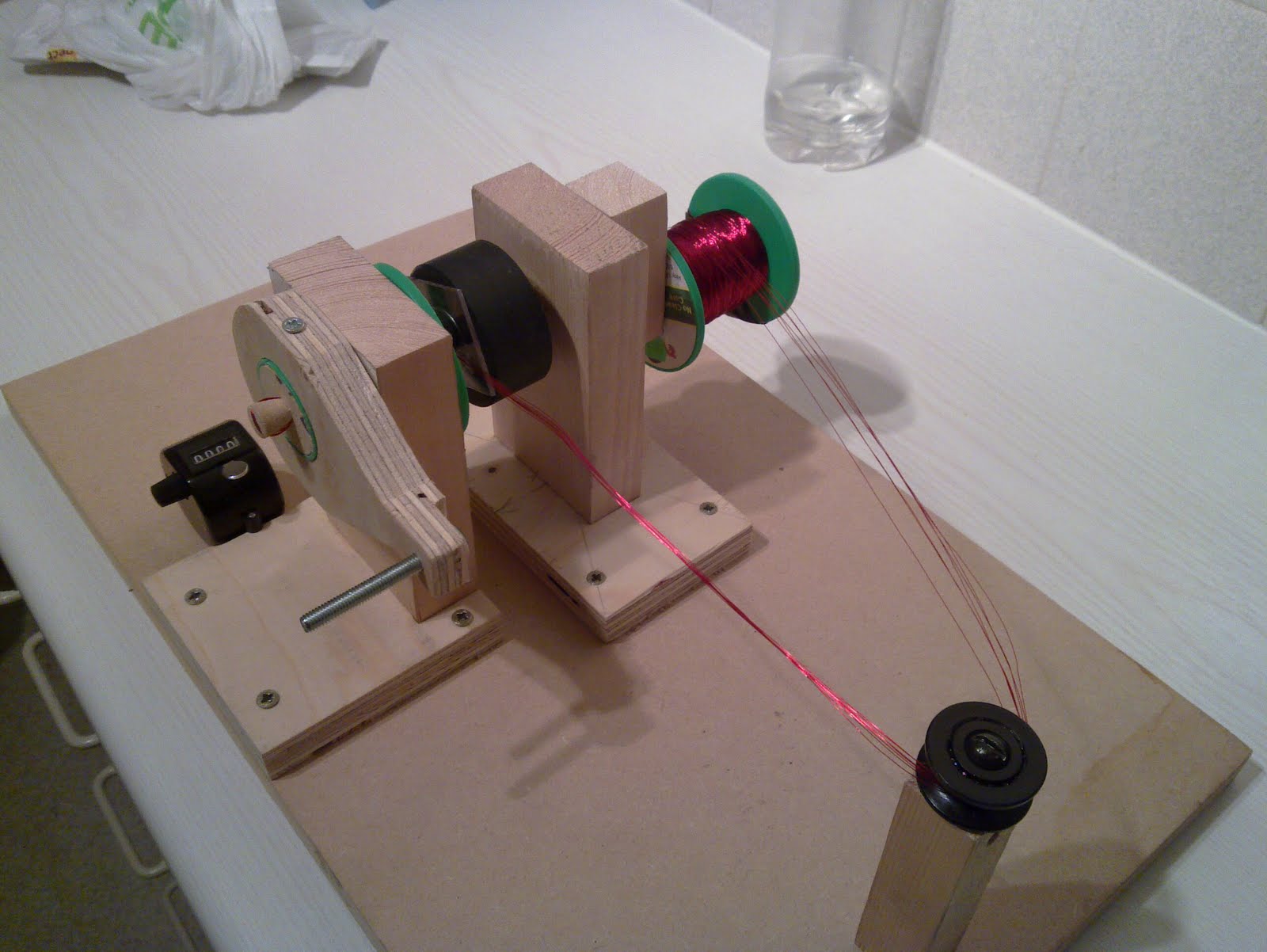


Here is the finished article:
Nylon bolts at each corner, 335 turns of 7 strand untwisted 0.2mm, AM antenna ferrite core. I found it much easier to wind a good coil without twisting the strands into a bundle. It winds like a tape when untwisted and sits very nicely with minimal crossovers.


Rotor
I have acquired some empty surface-mount reels, 33cm diameter, 13mm centre hole, range of thickness'

I asked a local engineering company for a quote for an acrylic rotor as per romero's spec (250mmx10mm) with milled magnet holes. The price they quoted me was way above what I was prepared to pay for a first try-out, so I will be creating my own. If we need to roughly check lots of different rotor magnet combinations I will use these spools, maybe filled with expanding foam to make them rigid.
My rotor will be constructed from salvaged 12mm polycarbonate.

Here is a blank cut with a black&decker router, I just need to mark up the magnet holes and the centre hole for drilling

Using these thermo-plastic bearing housings and 12mm stainless steel shaft
More to come.